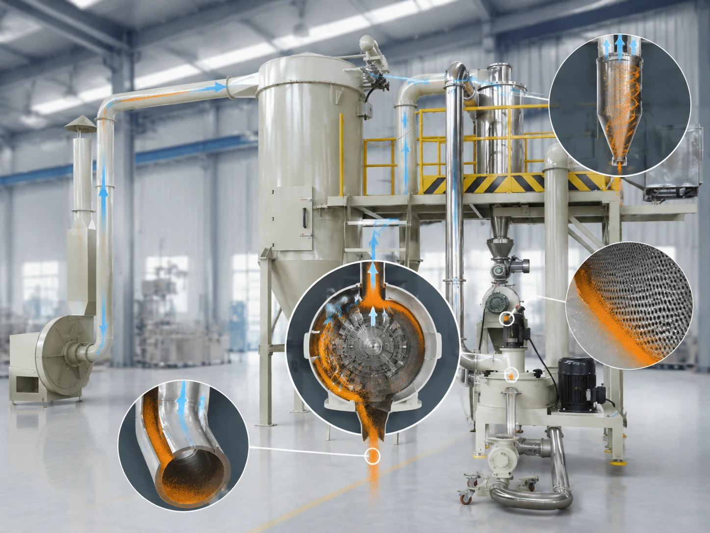
Powder buildup inside an ACM mill rarely starts with a complete blockage. It appears as a thin layer behind the classifier wheel, a deposit near the outlet, or a slow rise in motor current. Output falls. Particle size drifts. In most cases, heat, airflow, feeding, material condition, or mechanical wear has moved outside the stable range.
What Causes Powder to Build Up Inside an ACM Mill?
The deposit itself provides clues. Loose dust suggests weak airflow; a hard or glossy layer usually suggests heat.
Excessive Heat and Softening of the Powder
Grinding creates heat. If process air cannot remove it quickly enough, resin particles soften and stick to the liner, rotor, classifier wheel, or discharge area.
A common pattern appears after several hours: outlet temperature rises while throughput falls. Hot extruded chips can cause the same result, so chips should be fully cooled before grinding.
Moisture, Cohesive Feed and Fine Particles
Moisture increases cohesion. Condensation in a hopper or damp storage conditions may create soft agglomerates that smear against internal surfaces.
Fine particles collect around seals, joints, and low velocity areas. Once a thin layer forms, more powder attaches to it. Uneven chip size also creates short periods of overload, even when the average feed rate looks acceptable.
Restricted Airflow and Mechanical Wear
Process air handles cooling, transport, classification, and discharge, which is why the stability of the air classification process matters as much as the condition of the grinding chamber. A blinded filter, overloaded cyclone, blocked sieve, restricted duct, or poor rotary valve can reduce airflow through the whole system.
Scratched liners, damaged seals, and worn classifier parts create retention points. Deposits that repeatedly form in one place deserve a mechanical inspection, not another quick wipe.
How Can Operators Detect Powder Buildup Before the Mill Becomes Blocked?
Watch for changes from the normal operating pattern:
- Rising motor current
- Higher outlet temperature
- Lower throughput at the same feeder setting
- Unstable vacuum or differential pressure
- More coarse particles or wider particle size variation
- New vibration, noise, or frequent sieve cleaning
Keep a baseline for each formulation: feed rate, current, classifier speed, temperature, pressure, and output. A small deviation may need a short inspection. Left alone, it may cost half a shift.
How Should Feed Material Be Prepared Before It Enters the ACM Mill?
Stable grinding begins upstream.
Extruded chips should be cool, dry, and reasonably uniform. A correctly selected powder coating cooling belt should bring the extrudate down to a stable temperature before crushing and milling. Oversized lumps need to be removed or crushed. Sticky, partially fused, or damp material should not be sent into the mill to “see if it passes.” It usually does not pass cleanly.
The feeder should deliver a continuous flow. Sudden surges fill the grinding zone faster than the air system can transport material. Motor load rises, circulation increases, then temperature follows.
Storage matters too. Chips kept near a warm production area may enter the mill hotter in the afternoon, although the settings are unchanged.
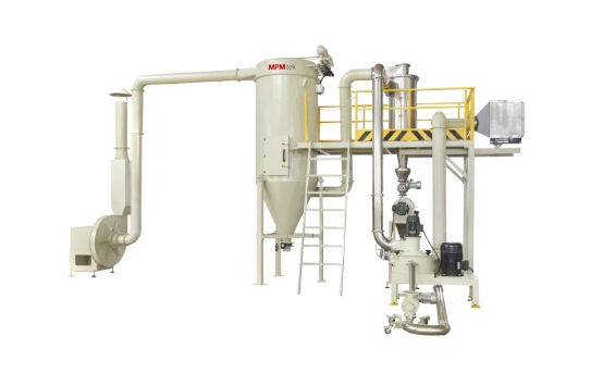
Which ACM Mill Settings Help Prevent Powder From Sticking?
No single setting prevents buildup. Airflow, feed rate, rotor speed, classifier speed, and temperature must remain balanced.
How Should Airflow and System Pressure Be Controlled?
Airflow must remove both powder and heat. Filters, ducts, cyclone sections, air inlets, and discharge components should remain clear.
Monitor pressure during production, not only after output drops. Restricting airflow to chase a finer product can increase residence time and internal loading. A finer powder is not useful when the mill must be opened twice per shift.
How Should Feed Rate, Rotor Speed and Classifier Speed Be Balanced?
Increase feed gradually while watching current, temperature, and pressure. The feeder setting alone does not show the real load.
Higher rotor speed adds grinding energy and heat. Higher classifier speed may keep coarse particles circulating longer. Raising both without enough airflow is a familiar route to buildup.
When current and temperature rise together, reducing feed is usually the sensible response. Increasing speed may recover output briefly, but often leaves a harder deposit.
How Can Grinding Temperature Be Kept Stable?
Stable temperature depends on cool process air, clean filters, steady feeding, and reasonable loading. Trend outlet temperature rather than watching only an alarm limit. Heat sensitive formulations may need cooler inlet air or lower throughput in hot weather.
A mill running slightly below maximum capacity often produces more usable powder over a full shift.
What Is the Correct Way to Clean Powder Buildup From an ACM Mill?
Stop feeding and allow the system to clear residual material. Isolate all energy sources under the approved lockout procedure. Follow site dust and explosion safety rules before opening the mill.
Clean the complete product path:
- Vacuum the chamber, rotor, liner, and classifier area.
- Inspect air inlets, discharge passages, ducts, cyclone, sieve, and filters.
- Remove deposits from joints, corners, seals, and behind removable parts.
- Check for scratches, worn edges, damaged seals, and loose components.
Hard metal scrapers can damage surfaces and create new retention points. Do not introduce water or cleaning liquid unless the equipment is designed for wet cleaning. Before restart, confirm correct assembly and free rotation.
What Preventive Maintenance Schedule Reduces Repeat Buildup?
Maintenance frequency should match the formulation, operating hours, fine powder level, and color change frequency.
Record current, temperature, pressure, and throughput each shift. Inspect retention areas after difficult batches or color changes. Check filters, sieves, air inlets, and rotary valves regularly. During planned shutdowns, examine classifier blades, grinding elements, liners, seals, and duct connections.
Photograph repeated deposits. Their shape and position are often more useful than a note saying “mill dirty.”
When Does Powder Buildup Indicate a Larger Equipment Problem?
Buildup that returns soon after cleaning is not a cleaning problem.
The fan or filter may be undersized. The mill may be operating beyond its practical capacity. The configuration may not suit a heat sensitive or highly reactive formulation.
Persistent high temperature at reduced feed, unstable negative pressure, uneven wear, or repeated deposits justify a system review. Evaluate the feeder, mill, cyclone, sieve, filter, fan, ducting, and controls together.
When the restriction involves more than the mill, the complete powder coating production line solution should be reviewed rather than replacing individual components in isolation.
Conclusion: How Can Manufacturers Keep an ACM Mill Clean and Productive?
A clean ACM mill usually comes from cool and uniform feed, sufficient airflow, balanced speeds, controlled loading, and attention to operating trends. When buildup continues, the process or equipment configuration needs closer examination.
Contact MPMtek to assess the formulation, target particle size, capacity, and color-change schedule, and discuss a suitable ACM grinding system or complete powder coating production line.
FAQ
Q: How often should an ACM mill be cleaned?
Inspect it after color changes, sticky formulations, abnormal temperature increases, or noticeable output loss. A fixed calendar interval alone is rarely enough.
Q: Can increasing airflow remove existing buildup?
It may clear loose powder, but compacted or softened deposits normally require shutdown and physical cleaning.
Q: Why does buildup occur only with certain formulations?
Resins, pigments, fillers, and additives change softening behavior, flowability, electrostatic tendency, and grinding response. A stable setting for one formula may fail with another.
Q: Can worn parts cause repeated buildup?
Yes. Scratches, worn liners, damaged seals, and uneven classifier components create retention points and disturbed airflow.